Introduction to Hybrid Output Capacitors
Introduction to Hybrid Output Capacitors
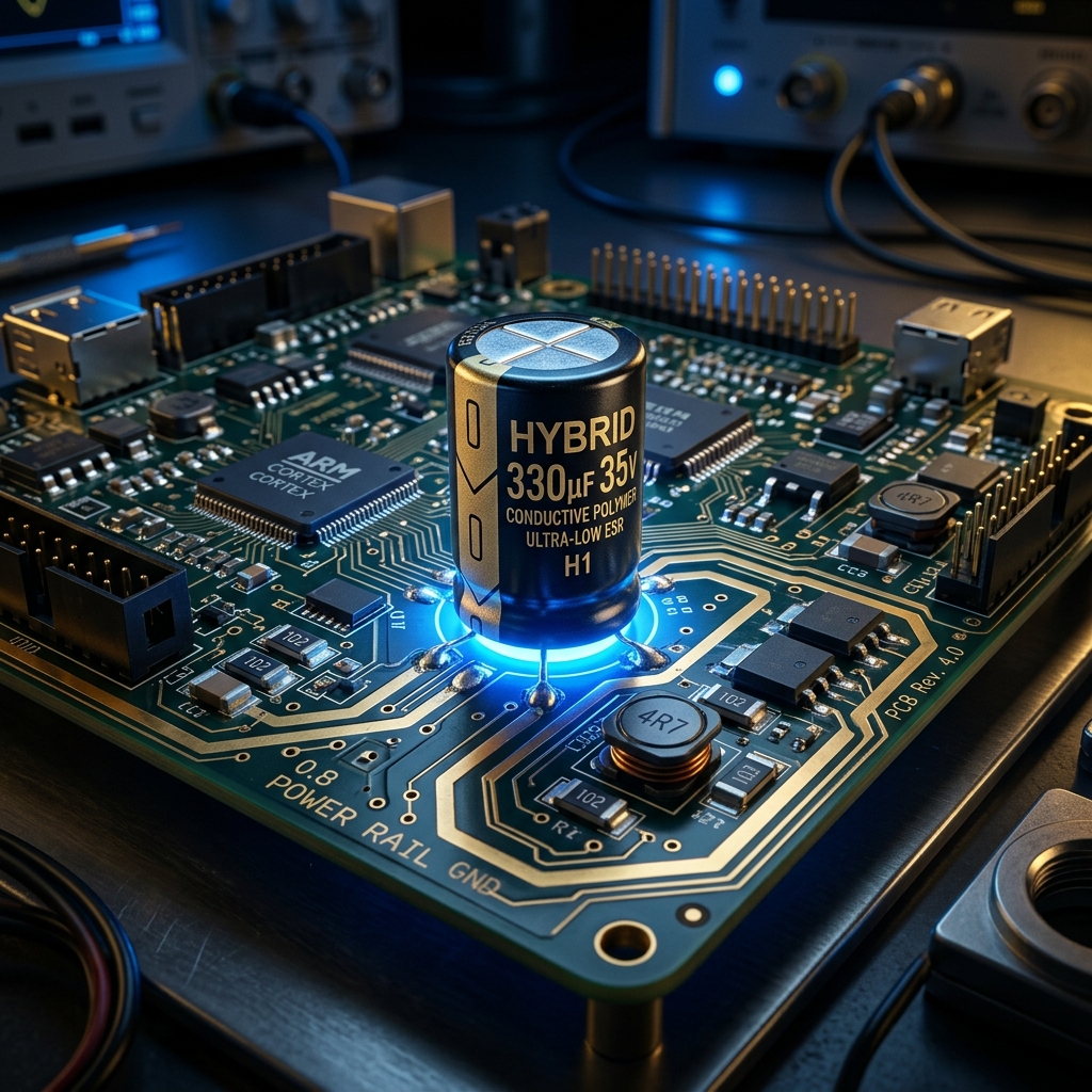
In modern hardware engineering, particularly when designing Power Delivery Networks (PDNs) for high-performance ICs like FPGAs, the term "Hybrid Capacitor" generally refers to Conductive Polymer Hybrid Aluminum Electrolytic Capacitors.
These advanced components bridge the gap between two older technologies, offering a "best of both worlds" solution for switching regulator output stages.
1. What is a Hybrid Polymer Capacitor?
A physical hybrid capacitor combines two different materials within the same capacitor casing:
- Solid Conductive Polymer: Provides extremely low Equivalent Series Resistance (ESR) and excellent high-frequency performance.
- Liquid Electrolyte: Provides high capacitance density, lower leakage current, and a unique "self-healing" property where the liquid can repair micro-damage to the dielectric layer over time.
Key Advantages for Power Supply Design
* Massive Ripple Current Handling: Thanks to the ultra-low ESR of the solid polymer, these capacitors can absorb massive amounts of switching ripple current without overheating.
* No DC Bias Effect: Unlike Ceramic Capacitors (MLCCs)—which can lose up to 70% of their stated capacitance when a DC voltage is applied—hybrid capacitors maintain their full capacitance under load.
* No Piezoelectric Noise: Ceramic capacitors can physically vibrate and emit an audible whine under high ripple. Hybrid capacitors do not suffer from this.
* Space Efficiency: Because one hybrid capacitor has such high performance, a single unit can often replace a bulky array of 4 to 5 standard wet electrolytic capacitors, saving massive amounts of PCB area.
2. Component vs. Network (An Important Distinction)
It is crucial to differentiate between a physical hybrid component and a circuit topology concept:
* Hybrid Polymer Capacitor (Component): A single physical part you solder to the board that contains mixed liquid/solid materials inside.
* Hybrid Capacitor Network (Circuit Topology): A design strategy where you place *different types* of physical capacitors in parallel on your schematic.
* *Example:* Placing a large bulk Aluminum Electrolytic capacitor (high capacitance, high ESR) in parallel with tiny Ceramic MLCCs (low capacitance, ultra-low ESR).
3. Stability: The Load Pole and ESR Zero
When designing a buck converter, the output capacitors interact with the load to affect the stability of the control loop.
* The Load Pole: In control theory, a "pole" is a frequency where the power supply's ability to react starts to roll off (lag). The combination of the output capacitance ($C_{out}$) and the resistance of the FPGA load ($R_{load}$) acts as an RC low-pass filter, creating this pole.
* The ESR Zero: The Equivalent Series Resistance (ESR) of the capacitor creates a "Zero" (the mathematical opposite of a pole), which actually helps push back against the phase delay and improves stability.
When you use a Hybrid Capacitor Network (mixing different types of capacitors in parallel), calculating the exact frequencies of the Load Pole and ESR Zero becomes highly complex. IC manufacturers (like Texas Instruments) provide complex application notes specifically to help engineers calculate these values so they can correctly tune the buck converter's compensation network and prevent the power supply from oscillating.
4. Industry Standard Part Numbers
If you are looking to specify physical Hybrid Polymer Capacitors for a 5V, 12V, or 24V rail on an FPGA board, here are the industry-standard go-to components (assuming a common 25V, 100µF requirement):
* Panasonic EEH-ZA Series (e.g., EEH-ZA1E101XP): The gold standard for 105°C endurance and low ESR (30 mΩ).
* Nichicon GYA Series (e.g., GYA1E101MCQ1GS): Designed for extended operation at higher temperatures (up to 125°C).
* Rubycon PZA Series: A highly reliable alternative equivalent to the Panasonic and Nichicon offerings.