Inverting Amplifier
Output is phase-inverted. Gain = −Rf / Rin
Av = −Rf / Rin
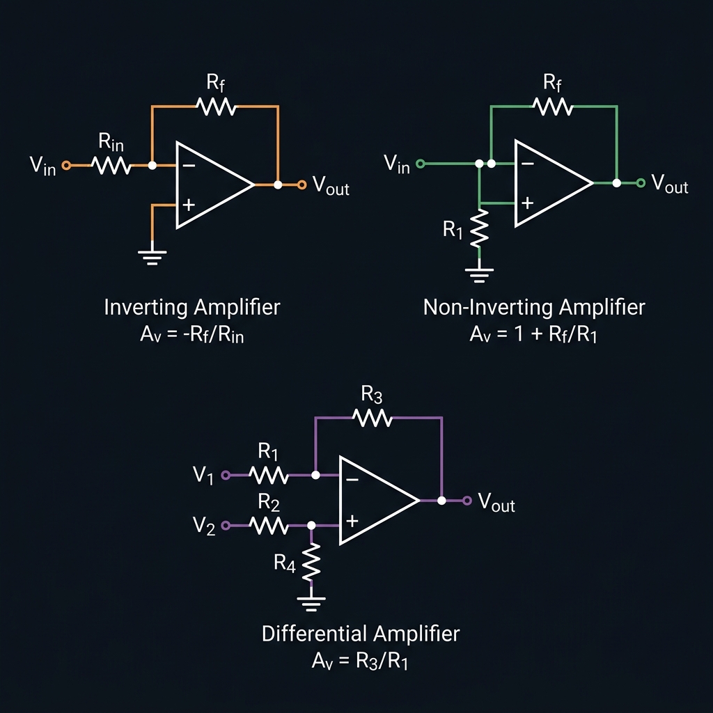
Understanding Op-Amp Gain Configurations
An operational amplifier (op-amp) can be configured in several ways to amplify signals. The three most common linear configurations are the inverting amplifier, the non-inverting amplifier, and the differential amplifier.
Inverting Amplifier
The input signal is applied to the inverting (−) terminal through Rin. The gain is set by the ratio of the feedback resistor Rf to Rin, and the output is inverted (180° phase shift). Common parts: LM358, TL072, NE5532.
Non-Inverting Amplifier
The input is applied to the non-inverting (+) terminal. The output is in phase with the input and the minimum achievable gain is 1 (unity gain buffer). Extremely high input impedance makes this ideal for sensor signal conditioning.
Differential Amplifier
Amplifies the voltage difference between two inputs while rejecting signals common to both (common-mode rejection). Used heavily in instrumentation and sensor interfaces. For best CMRR performance, use precision matched resistors.