Parameters
Value specified in the crystal's datasheet.
Parasitic capacitance from PCB traces and MCU pins. Typically 2pF - 5pF.
Understanding Crystal Oscillators and Load Capacitance
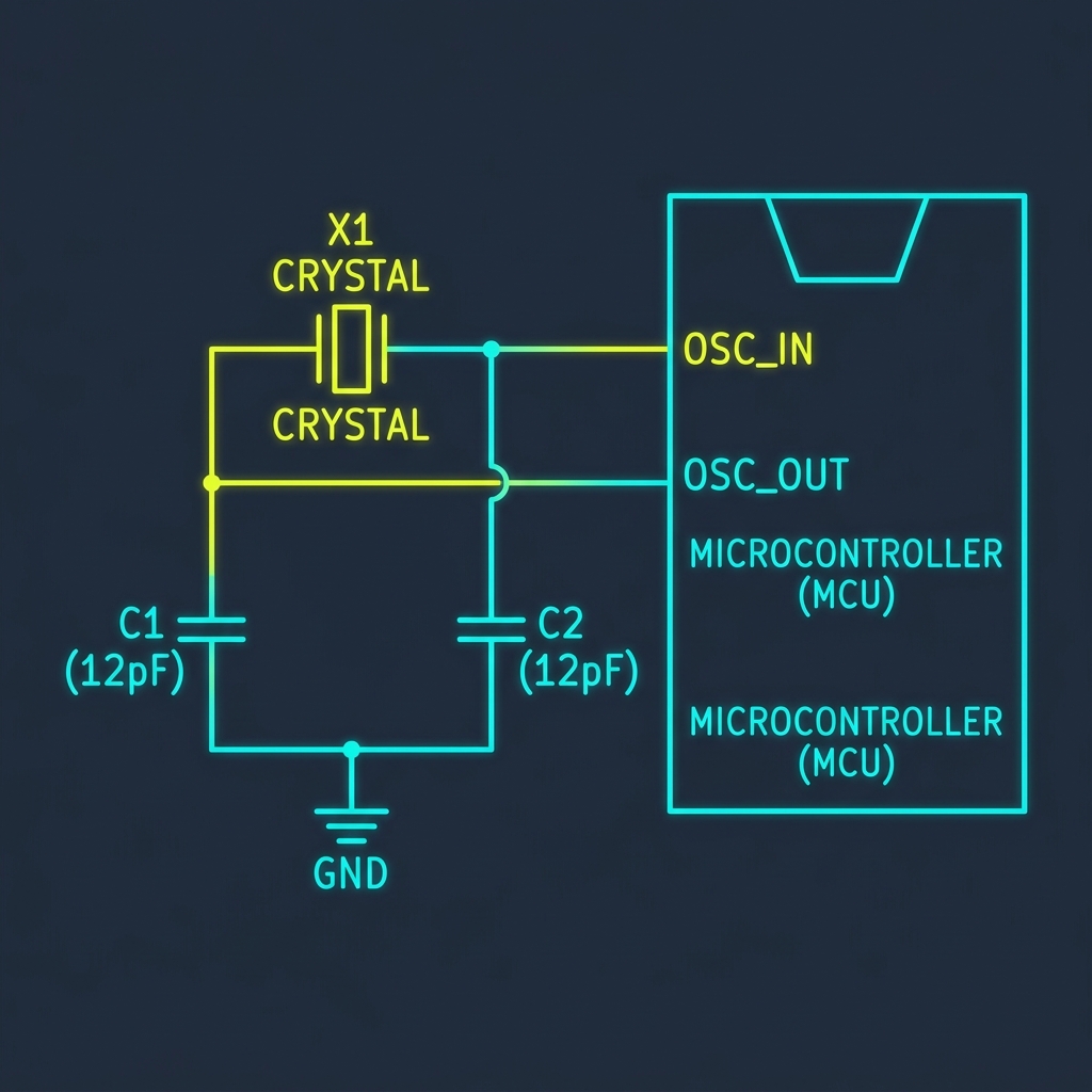
Quartz crystal oscillators are the heartbeat of modern digital electronics, providing precise clock signals for microcontrollers, FPGAs, and communication ICs. For a crystal to oscillate at its specified frequency accurately, it requires external "load capacitors" connected to ground on both of its pins. If the load capacitance is incorrect, the oscillation frequency will shift (pulling), or the crystal may fail to start oscillating entirely.
The total capacitance seen by the crystal is a combination of the two external capacitors (C1 and C2) in series, plus any parasitic "stray" capacitance from the PCB traces and the microcontroller pins. The formula used to calculate the ideal external capacitors is: C1 = C2 = 2 * (CL - Cstray). Stray capacitance typically ranges from 2pF to 5pF on a well-designed PCB.
Why Are Both Capacitors Equal?
In a standard Pierce oscillator configuration—the type built into almost all microcontrollers like the STM32 or ATmega series—symmetry is crucial. Using identical values for C1 and C2 ensures the phase shift through the feedback loop is perfectly balanced, which guarantees a rapid and reliable startup of the oscillation circuit under all temperature and voltage conditions.